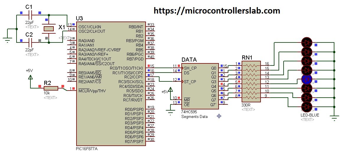
hbloknet Circuit Diagram To add more shift registers connect them like the second register. Always connect MR and OE pins directly to Arduino and DS pin to previous register. If you want to regulate the brightness of LEDs then connect potentiometer as shown in picture above to control resistance for all LEDs. However it is optional and you can get along without it.
In order to save on pins I am using a shift register to control the columns. This way I can control an almost unlimited number of columns with just four microcontroller pins. It is possible to use only three if the Enable Output pin is tied directly to voltage. I have selected the HEF4794 LED driver with shift register. By using a shift register, the LED chaser can control multiple LEDs with fewer output pins from the microcontroller. For example, a single shift register can control up to 8 LEDs with only 3 output pins from the microcontroller. while a microcontroller without a shift register may need 8 output pins to control the same number of LEDs.
Shift Register 74HC595 with Arduino Circuit Diagram
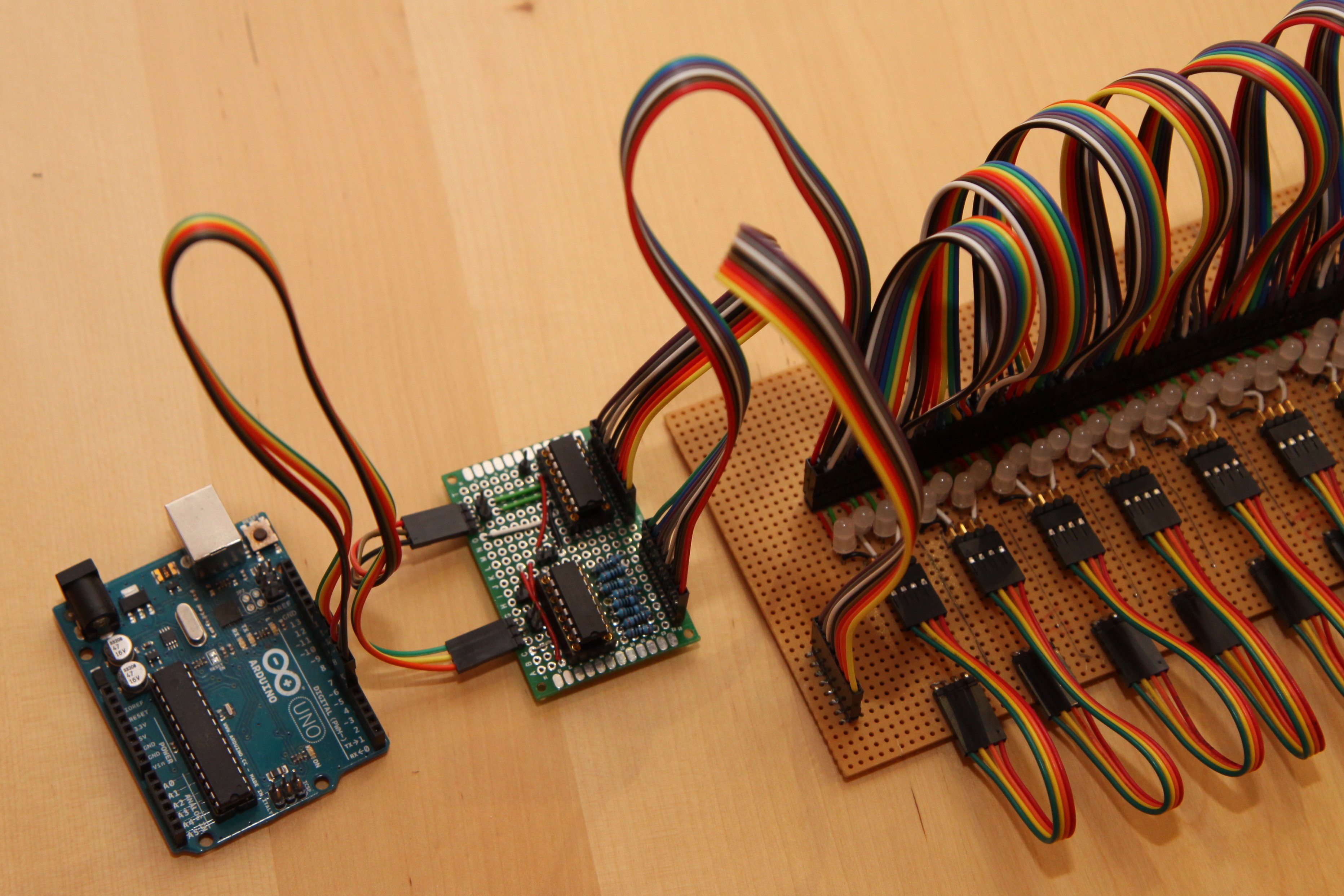
Using a Shift Register to Control a Bunch of LEDs. Shift registers are very useful tools; using a few pins connected to a shift register, we can increase the number of output data pins that are available to us. In this experiment, we'll be using a shift register to control eight LEDs, but we'll only be using three pins from the ATmega.

Connecting the shift register; Connecting the LEDs; Connecting your Omega; It's going to be similar to the second experiment, but this time we're going to use 8 LEDs and a shift register. Refer to the circuit building instructions in Experiment 2, except you will be connecting 8 LEDs to the shift register instead of the Omega's GPIOs.
LED Matrix Using Shift Registers : 7 Steps (with Pictures ... Circuit Diagram
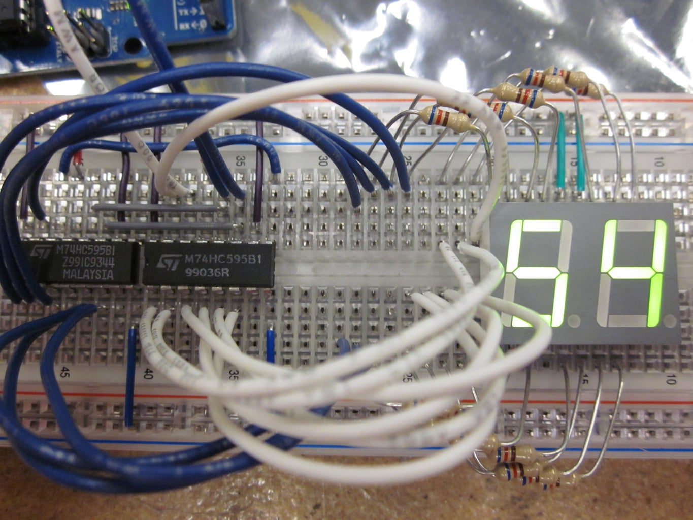
Code to Control LEDs using the 74HC595 Shift Register. Firstly, it allows you to control multiple outputs using only a few Arduino pins, which is especially useful when you have limited pins available. Secondly, it reduces the amount of wiring required, making your project more organized and easier to manage. 5.1 Using the 74HC595 Shift Register . In this lesson, we'll learn how to use the 74HC595 shift register to control multiple LEDs with just a few GPIO pins on the Raspberry Pi Pico 2. The 74HC595 is an integrated circuit (IC) that allows you to expand the number of digital outputs using a serial input.
