Digital Voltmeter for Power Supply Circuit Diagram In this project we have a tendency to design a circuit to build an electronic voltmeter while not making use of any microcontroller. Here we have a tendency to employing a very moderate IC for voltage activity particularly ICL7107/CS7107. Making use of ICL7107, we are able to build correct and really low price digital voltage measurement meter.

In order to measure voltages higher than the 5 V reference voltage, you need to divide the input voltage. Then the voltage actually input to the Arduino is 5 V or less. in this experiment, we will use a 10 kohm, along with a 90.9 kohm resistor, to create a 10:1 divider. This will allow us to measure voltages up to 50 V. Hardware Required

How to Make a Simple Digital Voltmeter with an Arduino Circuit Diagram
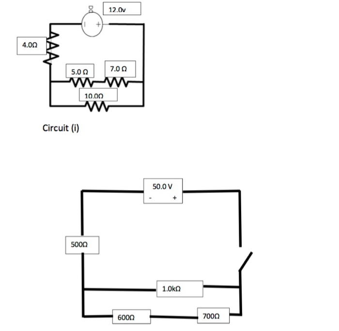
But to measure greater levels of voltage, something more is needed. To get an effective voltmeter meter range in excess of 1/2 volt, we'll need to design a circuit allowing only a precise proportion of measured voltage to drop across the meter movement. This will extend the meter movement's range to higher voltages.
The transistors are BC640, however you may try other transistors like 8550 or 187 etc. The proposed digital voltmeter, ammeter circuit module can be effectively used with a power supply for indicating the voltage and current consumption by the connected load through the attached modules. Referring to the circuit diagram below, the 3 digit digital display module is build through the ICs CA 3162 In this project, you will construct a simple analog multimeter. illustrated in Figure 1, which supports both voltage and current measurements. Figure 1. Illustration of the analog multimeter built in this project. Parts and Materials. Sensitive meter movement; Selector switch, single-pole, multi-throw, break-before-make

Basic Electronics Tutorials ... Circuit Diagram
We have made a video tutorial about this project. If you want to know the simple theory behind the coding, then do watch the following video. Follow the circuit diagram and make the following circuit. Step 4: It's Done! Let's wrap this up. Just plug in the battery or any voltage source to measure and you can see the voltage written on